The Ultimate Guide to Selecting Triaxial Plastic Geogrids for Subgrade Construction
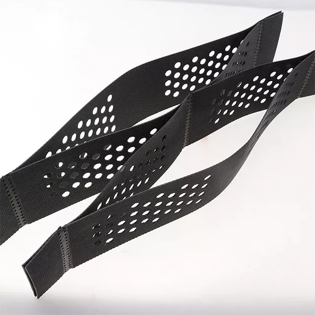
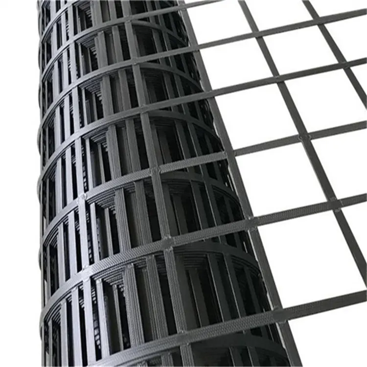
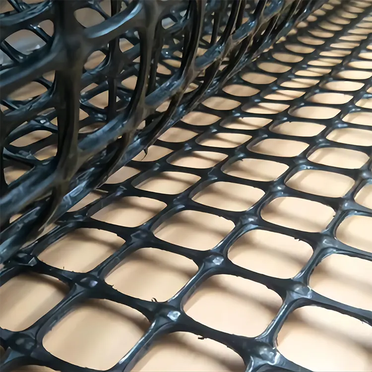
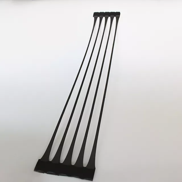
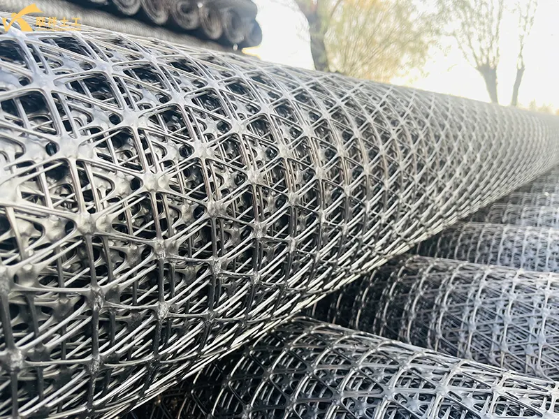
Triaxial plastic geogrid is a new product developed and improved based on uniaxial and biaxial plastic geogrids. The material is made of high-molecular polymer (polypropylene) through extrusion, stretching, sheet forming, and punching processes, followed by longitudinal, transverse, and Z-axis stretching. This product adds a third stretching direction to its three-dimensional structure. The core advantages of Lianxiang triaxial plastic geogrid are: significantly improving the bearing capacity of the subgrade, controlling uneven settlement, extending road service life, and reducing long-term maintenance costs through efficient reinforcement, isolation, and drainage.
1. Why choose triaxial geogrid for subgrade construction?
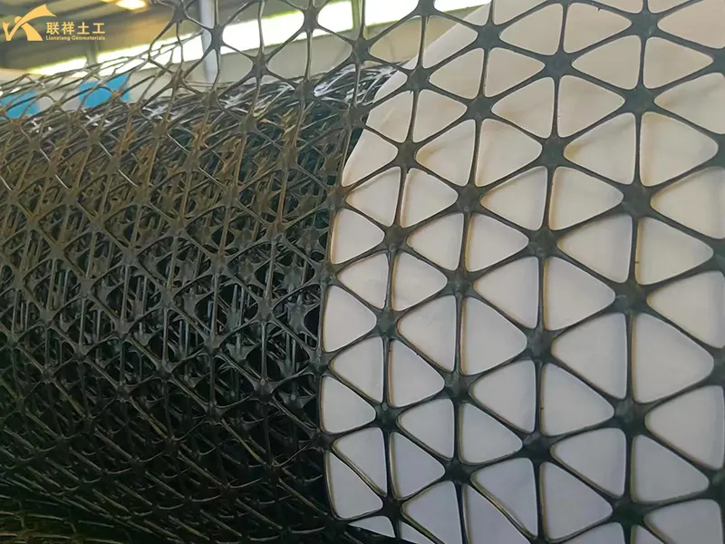
Triaxial plastic geogrid has a unique physical structure, significantly superior to other geogrids in tensile strength. More importantly, this structure integrates with the soil in three dimensions, thus preventing soil erosion in different directions and enhancing the prevention of subgrade settlement.
1.1. Superior Mechanical Properties and Reinforcing Effect
- High Strength and Low Creep: The plastic material and directional stretching process give it high tensile strength and low creep (i.e., minimal deformation under long-term loads), providing a durable and stable reinforcing effect.
- Unique "Interlocking" Mechanism: This is the core advantage of the triangular structure. When the grid is laid in the soil, the fill material (sand, gravel, soil) embeds itself in the triangular mesh, forming a strong "interlocking" effect.
- Effectively Distribute Loads: Distribute concentrated loads such as vehicle wheel loads over a larger area, reducing the pressure on the underlying soft soil.
- Restrict Lateral Displacement: Limit the lateral movement of the subgrade fill material under stress, thereby significantly improving the overall stiffness and stability of the subgrade.
1.2. Excellent Drainage and Consolidation Functions
- Three-Dimensional Permeable Structure: Unlike some planar grids, the triangular plastic grid provides a continuous three-dimensional drainage channel.
- Accelerated Drainage and Consolidation: In soft soil foundation treatment, it can quickly drain pore water from the foundation soil, accelerating the consolidation process and thus rapidly improving foundation strength and shortening the construction period.
1.3. Effective Isolation Effect
- Preventing Material Mixing: Laying between the subgrade and the foundation soil effectively prevents base course aggregates (such as crushed stone and gravel) from sinking into the underlying soft soil, while also preventing soft soil from flowing upwards into the base course.
- Maintaining Structural Layer Integrity: This isolation effect ensures the design thickness and integrity of each structural layer of the subgrade (base course, subbase course), allowing it to fully utilize its designed bearing capacity and avoiding structural layer failure due to material mixing.
1.4. Controlling Differential Settlement and Reflective Cracks
- Reducing Uneven Settlement: Through reinforcement and load dispersion, it can effectively reduce uneven settlement that is prone to occur at the junction of new and old subgrades and at the connection between bridge abutments and subgrades.
- Suppressing Reflective Cracks: In road widening or reconstruction, laying triangular plastic geogrids at the bottom of the base layer can absorb and reduce stress concentration at cracks in the underlying layer, preventing or delaying the upward reflection of cracks to the asphalt surface, thus extending the pavement's service life.
1.5. Simple Construction, High Overall Benefits
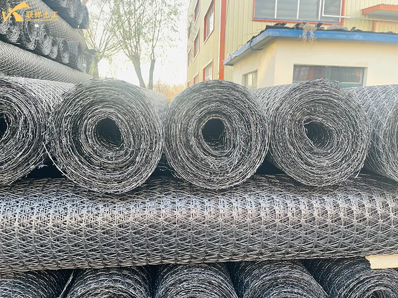
- Lightweight and Easy to Handle: The plastic material makes it very lightweight, and the roll form facilitates transportation and on-site handling.
- Simple Laying and High Efficiency: It can be laid quickly manually or mechanically, with simple splicing and low requirements for construction equipment, significantly improving construction efficiency.
- High Durability: Resistant to acid, alkali, and salt corrosion, resistant to microorganisms and insect infestation, and has a long service life.
- Reduced Filler Material Usage: Under the same bearing capacity requirements, the subgrade thickness can be appropriately reduced, saving filler material.
- Treatment of Poor Foundations: On soft soil foundations, using geogrids can avoid or reduce expensive deep foundation treatments such as replacement and piling.
- Extended Maintenance Cycle: Extending the road's service life directly reduces long-term maintenance and repair costs.
2. Relevant Parameters of Triaxial Plastic Geogrid
2.1. Laying Parameters
- Laying Direction: The main load-bearing direction (usually longitudinal) must be consistent with the road traffic direction. Diagonal ribs help disperse lateral stress.
- Laying Tension: During laying, the geogrid must be straightened and leveled. The tension should be controlled at 5-10 kN/m to avoid wrinkles or loosening that could affect stress transfer.
- Laying Layer Position: Depending on the road structure design, it is usually laid between the top and bottom base courses of the subgrade or in the soft soil foundation treatment layer, at least 15 cm from the bottom of the pavement structure layer.
2.2. Fixing Parameters
- Fixing Method: Use U-shaped nails, steel piles, or geogrid-specific fixing nails. For soft soil foundations, the fixing can be densified.
- Fixing Spacing: Longitudinal fixing spacing is 2-3 m, and transverse spacing is 1.5-2 m; the fixing spacing at the edges is reduced to 1-1.5 m to prevent edge curling.
- Fixing Depth: The fixing nails should be inserted into the soil to a depth of at least 15 cm to ensure a firm bond with the soil.
2.3. Overlap Related Parameters
- Overlap Width: Longitudinal overlap width not less than 20cm, transverse overlap width not less than 15cm; for complex road sections (such as intersections, steep slopes), the overlap width can be increased to 25-30cm.
- Overlap Method: Welding or binding is preferred for fixing, with binding point spacing of 50-80cm to ensure continuous stress at the overlap.
- Overlap Direction: The overlap joint must be perpendicular to the direction of stress to avoid stress concentration caused by being parallel to the principal stress direction.
2.4. Filler Matching Parameters
- Filler Particle Size: The maximum particle size of the filler covering the grid should not exceed 5cm to avoid sharp particles puncturing the grid.
- Compaction Requirements: The filler must be compacted promptly after laying, with a compaction degree of not less than 95% (heavy compaction standard). Compaction machinery should avoid directly rolling over the grid.
- Filler Thickness: The thickness of the first layer of covering filler should not be less than 15cm to ensure that the grid is not exposed and is not subject to mechanical damage.
3. Fixing Methods for Three-Dimensional Plastic Geogrids
3.1. U-Shaped Nail Fixing (General Type)
- The most commonly used foundation fixing method, suitable for most subgrades (soft and hard soil).
- Use U-shaped nails made of galvanized steel bars or high-strength plastic, inserted into the soil to a depth ≥15cm. Fixing spacing is as mentioned before: longitudinal 2-3m and transverse 1.5-2m.
3.2. Reinforced Pile Fixing (Reinforced Type)
- For soft soil foundations, steep slopes, or geogrid edges requiring stronger fixing force.
- Reinforced piles are 12-16mm in diameter and 30-50cm in length, inserted vertically into the soil at intervals of 1-1.5m. They can be connected to the geogrid using binding tape.
3.3. Binding Fixing (Overlap-Specific)
- Primarily used for auxiliary fixing at geogrid overlaps, ensuring continuous stress at the overlap joint.
- Use geogrid-specific binding tape or galvanized iron wire, with binding points spaced 50-80cm apart, evenly distributed at overlaps to avoid omissions.
3.4. Welding Fixing (For Plastic Geogrids)
- Suitable for weldable plastic triaxial geogrids such as high-density polyethylene (HDPE).
- Use a hot air welding gun or specialized welding machine to weld the geogrid ribs at the overlaps together. The weld width should be ≥10cm, ensuring no incomplete welds or omissions.
3.5. Edge Press Fixing (Simple and Convenient Type)
- Suitable for gentle road sections, temporary construction, or scenarios where high fixing strength is not required.
- Use gravel, bricks, or precast concrete blocks to press onto the edges or overlaps of the geogrid. The edge pressing material should be ≥15cm thick, ≥30cm long, and spaced 1.5-2m apart.
4. Construction and Acceptance Methods for Three-Dimensional Plastic Geogrid Projects
4.1. Material Arrival Acceptance (Basic Prerequisite)
- Appearance Quality: The geogrid should be free from damage, tears, and obvious wrinkles. Ribs should be flat, joints should be secure, and there should be no missing edges, corners, or discoloration due to aging.
- Specifications: Rib width, thickness, spacing, and overall geogrid dimensions must be consistent with the design documents, with an allowable deviation of ≤±5%.
- Quality Certificates: Provide a factory certificate of conformity and test report. Key indicators (tensile strength, elongation at break, creep performance) must meet design requirements. On-site sampling and re-inspection may be necessary.
4.2. Construction Process Acceptance (Core Aspect)
- Laying Acceptance: The laying direction should be consistent with the main load-bearing direction. The geogrid should be flat, without looseness or twisting, with 100% coverage and no missed or incorrect laying.
- Fixing Acceptance: The fixing method should meet design requirements. U-shaped nails/reinforcing piles should be inserted to a depth ≥15cm, with a fixing spacing deviation ≤±10cm, and no edge curling or displacement.
- Overlap Acceptance: Overlap width ≥ 20cm longitudinally and ≥ 15cm transversely; welds/ties at the overlap are secure, with no incomplete welds or missing ties; the overlap joint is perpendicular to the direction of stress.
4.3. Post-Completion Performance Acceptance (Final Result)
- Subgrade Compaction: Compaction degree of the fill material above the geogrid ≥ 95% (heavy compaction standard), with no obvious settlement or local bulges.
- Geogrid Integrity: No mechanical damage, no puncture damage, exposed geogrid is completely covered, and there is no long-term exposure.
- Overall Stability: No slippage on the subgrade slope, pavement (or base course) flatness meets standards, and there are no cracks or subsidence caused by improper geogrid fixing.
5. Other Application Areas of Triaxial Plastic Geogrids
5.1. Railway Engineering
- Application Scenarios: Railway subgrade base reinforcement, track mattress laying, soft soil subgrade treatment.
- Core Function: Distributes train load, suppresses uneven subgrade settlement, prevents track displacement and deformation, and improves track smoothness and durability.
- Suitable Scenarios: Soft soil sections, embankment widening, or subgrade widening and reconstruction projects for high-speed and conventional railways.
5.2. Water Conservancy Engineering
- Application Scenarios: Auxiliary reinforcement of dam seepage prevention systems, riverbank/tidal flat protection, reservoir slope stabilization, and drainage ditch lining reinforcement.
- Core Function: Enhances the integrity of dam soil, resists water erosion and wave erosion, prevents soil seepage damage, and can improve seepage prevention when used with geomembranes.
- Suitable Scenarios: Reinforcement of small and medium-sized reservoirs, riverbank ecological revegetation, and coastal tidal flat protection projects.
5.3. Slope Protection
- Application Scenarios: Highway/railway slopes, mine revegetation slopes, foundation pit excavation slopes, and landslide control.
- Core Function: Constrains slope soil, prevents lateral slippage and collapse, provides a stable base for vegetation growth (in conjunction with vegetation slope protection), and enhances long-term slope stability.
- Suitable Scenarios: Steep slopes with a gradient ≥ 1:1.5, soft rock slopes, and ecological restoration areas after mining operations.
5.4. Port and Airport Engineering
- Application Scenarios: Port yard foundation reinforcement, wharf slope stabilization, airport runway/apron foundation treatment.
- Core Function: Bears concentrated loads from heavy equipment (such as container cranes) or aircraft, reduces the risk of foundation settlement, and enhances site bearing capacity.
- Suitable Scenarios: Port yards on soft soil foundations, airport expansion and renovation projects, and backfilled areas behind wharves.
5.5. Building and Foundation Engineering
- Application Scenarios: High-rise building foundation treatment, industrial plant floor foundation reinforcement, and shantytown renovation foundation improvement.
- Core Functions: Improves the bearing capacity of soft soil foundations, reduces building settlement and uneven deformation, and prevents wall cracking and floor bulging.
- Suitable Scenarios: Multi-story/high-rise buildings, heavy equipment workshops, and large-area flooring projects in soft soil areas.
6. Conclusion:
Triangular plastic geogrid, with their unique triangular three-dimensional structure and the excellent properties of plastic materials, play multiple roles in road construction, serving as a "reinforced framework," "drainage channel," and "isolation barrier." They are not only an effective technical means to solve traditional road engineering problems (such as soft soil, settlement, and cracking), but also a modern, cost-effective material that can improve project quality, accelerate construction progress, and achieve cost savings throughout the entire life cycle.
Written by
SHANDONG LIANXIANG ENGINEERING MATERIALS CO., LTD.
Kyle Fan
WhatsApp:+86 139 5480 7766
Email:admin@lianxiangcn.com
Contact
-
WhatsApp
-
E-MailE-Mail:admin@lianxiangcn.com
-
WeChatWeChat:18554180188

