Key Factors Affecting the Tensile Strength of Fiberglass Geogrid
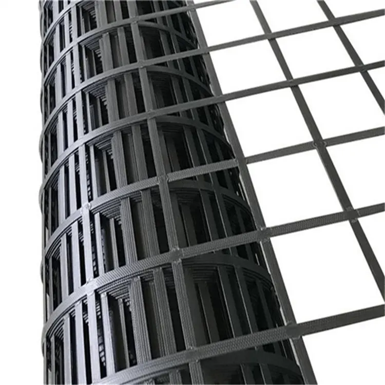
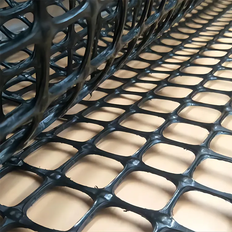
In the field of geogrids, fiberglass geogrids have been widely used in some special areas due to their high corrosion resistance, such as in soils with excessive acidity or alkalinity and in ultra-low temperature environments. However, in our practical applications, we are still more concerned about its tensile strength. Compared with steel-plastic geogrids, its tensile strength is lower, but we can improve its tensile strength through some methods. Today, I will first analyze what factors can affect its tensile strength. In fact, we can analyze the key factors affecting the tensile strength of fiberglass geogrids from four main aspects: raw materials, production process, structural design, and external environment.
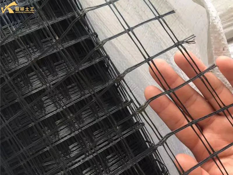
1. Raw Material Factors
The most fundamental factor determining product performance is undoubtedly the raw materials used in production. Impurities in the raw materials will certainly affect its quality. Lianxiang Geotechnical has very strict standards for the selection of raw materials for geogrids. Both fiberglass and coating materials must undergo strict quality inspection and acceptance by the company before they can be used.
1.1. Types and Properties of Glass Fibers:
- Glass Composition: Alkali-free glass fiber (E-Glass) is typically used, possessing high strength, high modulus, and good water resistance. Using medium-alkali or high-alkali glass fiber significantly reduces its strength and corrosion resistance. Alkali-free glass (SiO₂ content approximately 54%-56%, alkali metal oxides ≤0.8%) has a tensile strength of 3000-3500 MPa, far exceeding that of medium-alkali glass (1800-2200 MPa), and exhibits stronger water and chemical corrosion resistance, avoiding the strength reduction caused by alkali metal ion hydrolysis.
- Monofilament Strength: The strength of the glass fiber monofilament itself is fundamental. This depends on the purity of the molten glass, the stability of the drawing process, etc.
- Fiber Diameter: Generally, at the same tex (tex, unit of linear density), the more monofilaments (i.e., the finer the monofilament diameter), the better the fiber's flexibility and fatigue resistance, which is beneficial for maintaining strength.
- High-strength glass fiber (S-glass): The SiO₂-Al₂O₃-MgO system of S-glass increases its tensile strength to 4000-4800 MPa, 30%-40% higher than E-glass, but at a higher cost. It is suitable for projects with extremely high strength requirements, such as roadbeds and airport runways.
1.2. Improving the purity and uniformity of glass fiber
- Controlling raw material impurities: Strictly remove impurities such as iron and calcium from the glass raw materials (impurity content ≤0.1%) to avoid the formation of internal defects (such as bubbles and stones), which can lead to stress concentration and breakage under fiber stress.
- Optimizing fiber diameter and roundness: Using fine-diameter fibers (single filament diameter 8-12µm, conventionally 15-20µm), fine fibers have fewer surface defects and higher load-bearing capacity per unit area; at the same time, ensuring fiber roundness (roundness error ≤5%) avoids uneven stress distribution caused by irregular cross-sections.
1.3. Sizing Agent:
- Core function of the sizing agent: Improves the interfacial bonding between fibers and resin, reducing fiber slippage. Epoxy or polyurethane sizing agents should be selected (good compatibility with subsequent coating resins), avoiding paraffin-based sizing agents (weak interfacial adhesion).
- Sizing agent dosage control: The sizing agent dosage should be 2%-4% of the fiber mass. Too much will lead to "over-bonding" between fibers, causing overall breakage under stress; too little will fail to form an effective interfacial bond, making the fibers prone to dispersion and slippage.
1.4. Coating Material:
The coating is a crucial step, serving not only as a protective layer but also as a stress transfer medium.
- Adhesion: The coating (usually modified bitumen, PVC, or other polymers) must have extremely strong adhesion to the glass fiber bundle. Insufficient adhesion will cause the fibers to separate from the coating under stress (debonding), resulting in insufficient overall strength.
- Coating Thickness and Uniformity: A coating that is too thin provides insufficient protection, making it susceptible to punctures by aggregates or corrosion in acidic or alkaline environments; a coating that is too thick is uneconomical and may alter the mechanical properties of the geogrid. A uniform coating is essential to ensure even stress distribution across all fibers.
2. Manufacturing Process Factors
While high-quality raw materials are fundamental to producing high-quality products, advanced manufacturing processes are also necessary. Therefore, to achieve high tensile strength in fiberglass geogrids, the manufacturing process must be scientifically rigorous. Especially in the fiberglass geogrid production process (fiber drawing → weaving → coating → molding), deviations in process parameters can lead to fiber damage and structural loosening, requiring precise control to improve tensile strength.
2.1. Optimizing Fiber Drawing Process
- Controlling Drawing Temperature and Speed: The drawing temperature is stabilized at 1200-1250℃ (E-glass) to avoid uneven crystallization within the fiber due to temperature fluctuations; the drawing speed is controlled at 800-1200m/min. Excessive speed can lead to overstretching and microcracks, while insufficient speed results in insufficient fiber density.
- Optimizing Cooling Method: A combined air-cooling and water-cooling system is used, with a cooling rate ≥500℃/s, to rapidly solidify the fiber structure and reduce residual internal stress.
2.2. Improved Weaving Process (Core Impact on Stress Transfer in Grids)
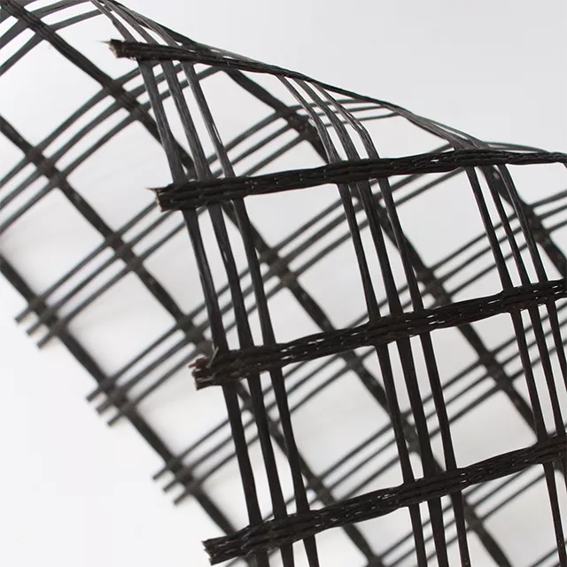
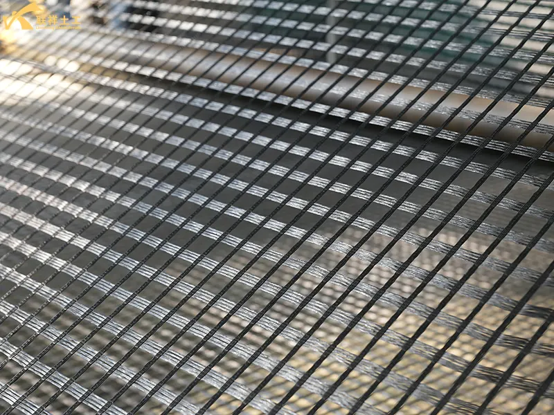
- Selection of High-Strength Weaving Structure: Prioritize warp-knitted directional structures (rather than machine-woven or weft-knitted structures). Warp knitting ensures straight alignment of warp and weft fibers, eliminating bending losses and resulting in 20%-30% higher tensile strength compared to machine-woven grids. Key nodes utilize "double warp double weft" or "triple warp triple weft" interlacing to enhance tear resistance.
- Precise Control of Weaving Density: Adjust the number of warp and weft fibers according to design strength requirements (e.g., for a 200kN/m strength grid, warp fiber density ≥10 fibers/cm) to avoid stress concentration due to excessive fiber spacing. Simultaneously control weaving tension (warp tension 20-30N/fiber, weft tension 15-25N/fiber) to ensure uniform fiber stress distribution without slack or excessive stretching.
- Improving Node Strength: Nodes where warp and weft yarns intersect are weak points under stress. Advanced weaving techniques and coating curing ensure strong nodes, preventing grid separation and guaranteeing overall strength.
2.3. Optimize Coating and Curing Process
- Select High-Strength Coating Resin: The coating resin must possess both adhesive properties and intrinsic strength. Epoxy resin (tensile strength ≥ 80 MPa) or modified polypropylene (tensile strength ≥ 35 MPa) should be preferred over ordinary polyethylene (tensile strength ≤ 25 MPa). Adding 10%-15% glass microspheres or carbon fiber powder can further enhance the strength of the resin matrix.
- Control Coating Thickness and Uniformity: The coating thickness should be 0.3-0.8 mm. Excessive thickness increases the weight of the grid and makes it prone to cracking, while insufficient thickness fails to effectively encapsulate the fibers. A "dip coating + extrusion coating" composite process should be used to ensure complete resin penetration into the fiber gaps, eliminating bubbles and missed areas.
- Precisely Control Curing Parameters: Epoxy resin should be cured at 80-100℃ for 15-20 minutes; polypropylene should be cooled at a rate ≥ 30℃/min after coating to prevent uneven resin crystallization leading to interfacial delamination, ensuring an integrated load-bearing structure between the fiber and resin.
3. Chemical or Physical Modification Treatment
Chemical or physical methods are used to improve the fiber and structural properties. Modification techniques are employed to enhance interfacial bonding and damage resistance, targeting the surface characteristics of glass fibers and the overall structure of the grid.
3.1. Glass Fiber Surface Modification (Core Enhancement of Interfacial Bonding with Resin)
- Chemical Modification: The fiber surface is treated with a silane coupling agent (such as KH-550, KH-560). The siloxane groups of the coupling agent react with the hydroxyl groups on the fiber surface to form chemical bonds, and the other end bonds with the resin molecular chain, increasing the interfacial bonding strength by 30%-50%. The treatment concentration is 1%-3%, the soaking time is 10-15 min, and the drying temperature is 110-120℃.
- Physical Modification: Plasma treatment (argon or oxygen plasma, power 300-500W, time 3-5 min) or corona treatment (voltage 15-20kV) increases the fiber surface roughness (reducing the surface contact angle from 70° to below 30°), improving the resin's wettability on the fiber surface and reducing interfacial slippage.
3.2. Overall Modification of the Grating (Enhancing Anti-aging and Structural Stability)
- Anti-aging Modification: Add 2%-3% of a UV absorber (e.g., UV-531) and 1%-2% of an antioxidant (e.g., 1010) to the coating resin to prevent resin degradation during long-term outdoor use, which leads to a decrease in grating strength (unmodified gratings lose approximately 20% of their strength after 5 years, while modified gratings can reduce this to less than 5%).
- Toughening Modification: Add 5%-8% of an elastomer (e.g., nitrile rubber, EVA) to the resin to improve the grating's impact resistance and flexibility, preventing strength loss due to brittle fracture under stress.
- Nanotechnology Modification: Add 1%-3% of nanomaterials such as carbon nanotubes and graphene, utilizing their high specific strength characteristics to strengthen stress transfer at the resin matrix and fiber interface, increasing the tensile strength of the grating by 15%-25%.
4. Product Structural Design Factors
Utilizing the stability principles of structure in mathematics and geometry, the geogrid's geometry can be designed as a triangular or trapezoidal shape with uniform stress and high stability, maximizing fiber strength to enhance its tensile strength. Contact our geotechnical team for professional design expertise and extensive experience in geogrid shape design. Please feel free to contact us for any related inquiries.
4.1. Optimizing Geogrid Aperture and Shape
- Aperture Design: Use rectangular or square apertures (20mm×20mm, 30mm×30mm) to avoid stress concentration caused by circular apertures. Excessively large apertures (≥50mm) reduce structural integrity, while excessively small apertures (≤10mm) increase weight and hinder soil adhesion. The aperture must be matched to the specific engineering scenario (30mm×30mm is commonly used for subgrade engineering, and 20mm×20mm is commonly used for pavement engineering).
- Edge Structure Design: The edges of the grid are treated with "edge binding" (additional resin coating or braided reinforcement) to prevent the edge fibers from loosening after construction and cutting, which would lead to a loss of tensile strength (the strength loss of an unbound grid edge is approximately 15%, while with edge binding, it can be controlled to within 5%).
4.2. Directional Reinforcement Design (for asymmetric stress scenarios)
- For scenarios such as roadbeds and slopes where "warp force is dominant," a "warp fiber reinforcement" design is adopted: S-glass fibers are used in the warp direction, and E-glass fibers are used in the weft direction. The warp fiber density is 20%-30% higher than that in the weft direction, increasing the strength of the grid in the dominant stress direction by 40%-60%.
- Multi-layer Composite Structure: A "double-layer fiber + intermediate resin interlayer" structure is adopted. The two layers of fibers are staggered (90° angle), and short-cut glass fibers are added to the intermediate interlayer to improve the shear resistance and overall tensile stability of the grid, increasing the strength by 30%-50% compared to a single-layer structure.
5. Application and Support Optimization
The final tensile strength of the geogrid depends not only on the product itself but also on the construction method. Therefore, we must avoid strength loss during construction and use, and reduce on-site losses through scientific and reasonable construction methods.
5.1. Pre-construction Treatment
- Geogrid Cutting: Use specialized tools (such as fiberglass cutters) to avoid using ordinary scissors, which can cause fiber fuzzing and breakage. Temporarily wrap the cut edges (with tape or resin) to prevent fiber loosening during transportation and laying.
- Substrate Treatment: The laying surface must be flat, and sharp stones, rebar, and other debris must be removed (protrusion height ≤ 5mm) to prevent the geogrid from being punctured under stress, leading to localized strength failure.
5.2. Laying and Fixing Process
- Laying Direction: Ensure that the longitudinal direction (high-strength direction) of the geogrid is consistent with the dominant stress direction (such as the longitudinal direction of the roadbed or the normal direction of the slope surface). Avoid laying in the opposite direction, which can reduce tensile strength by more than 50%.
- Overlap and Fixing: The overlap width should be ≥15cm, fixed with overlap nails (spaced 20-30cm) or geotextile stitching to prevent slippage at the overlap; fixing points should be evenly distributed to prevent local stress concentration that could lead to geogrid tearing.
5.3. Backfill and Compaction Control
- Backfill Material: Graded sand and gravel (particle size ≤20mm) should be used preferentially, avoiding the use of crushed stone containing sharp particles (particle size ≥30mm) to reduce mechanical damage to the geogrid.
- Compaction Parameters: Static rollers should be used for compaction (vibratory rollers should be avoided), with a compaction degree controlled above 95% and a compaction speed ≤2km/h to avoid excessive stretching or tearing of the geogrid during compaction.
6. External Environment and Usage Conditions
The usage environment is a key factor affecting the tensile strength of the geogrid. Maintaining high tensile strength during use is crucial for both project quality and the service life of the geogrid. Therefore, Lianxiang Geotechnical takes every possible measure to eliminate or mitigate the impact of the environment during on-site construction and subsequent maintenance.
6.1. Environmental Corrosion
- Acid and Alkali Environments: Glass fiber is not resistant to strong alkalis. In cement concrete (a highly alkaline environment), if the coating protection is insufficient, the glass fiber will corrode, and its strength will drop sharply. Therefore, geogrids used in concrete require a particularly excellent alkali-resistant coating.
- Long-Term Creep: Although the creep performance of glass fiber is far superior to that of plastic geogrids, slight deformation will still occur under long-term continuous loads. Long-term strength must be considered in the design.
6.2. Aging:
- UV radiation, temperature changes, and wet-dry cycles accelerate the aging of the coating material. An aged coating becomes brittle, cracks, and loses its protective function for the glass fiber.
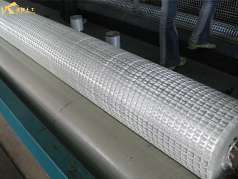
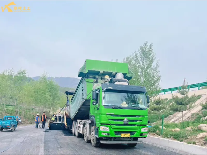
7. Conclusion
| Influencing Stage | Key Factors | Influencing Mechanism |
| Raw Materials | Glass Fiber Quality | Determines the theoretical upper limit of strength |
| Coating Materials and Adhesion | Protects fibers and transfers stress, forming the basis for achieving high strength | |
| Production Process | Weaving/Warp Knitting Structure | Affects node strength and overall structural stability |
| Coating and Curing Process | Determines the protective effect of the coating and the quality of bonding with the fibers | |
| Structural Design | Mesh Design, Fiber Orientation | Affects strength utilization efficiency and interaction with the soil |
| External Environment | Construction Damage | Causes physical damage, directly reducing strength |
| Chemical Corrosion (especially alkali) | Erodes the glass fiber itself, causing permanent strength loss | |
| Ultraviolet Radiation, Aging | Damages the protective coating, indirectly leading to fiber damage |
8. Related Questions
8.1 What is the typical lifespan of glass fiber geogrids?
A: The design service life of fiberglass geogrids can typically reach 50 years or more, even matching the design life of roads or structures (e.g., 50-100 years).
8.2 What are the international standards for the tensile strength of fiberglass geogrids?
A: There is no unified "fixed international standard value" for the tensile strength of fiberglass geogrids (GFGG). The core reason is that international standards (such as ISO, ASTM, and EN series) only specify test methods, performance grading rules, and minimum requirements. Specific tensile strength indicators need to be defined by product specifications based on the engineering application (e.g., roadbed, pavement, slope) and stress scenario (warp/weft). Furthermore, the test conditions (e.g., elongation benchmark, specimen size) differ between standards. It is necessary to first clarify the standard system before applying the corresponding indicators.
8.3 What are the three most authoritative international standard systems currently?
A: The three most authoritative international standard systems are ISO (International Organization for Standardization), ASTM (American Society for Testing and Materials), and EN (European Standards).
8.4 What materials are used for the coating of fiberglass geogrids?
A: The main coatings include modified asphalt coating, PVC coating, alkali-resistant coating, and modified polyester. Each has its own advantages; please consult us for details when purchasing products. Lianxiang Geotechnical's fiberglass geogrids will use appropriate coating materials according to customer needs.
In summary, the core logic for enhancing the tensile strength of fiberglass geogrids is: using high-performance fibers as a base, reducing structural defects through precise process control, strengthening interface bonding with modification technology, improving load-bearing efficiency with optimized structure, and avoiding on-site losses through standardized construction. In practical applications, the above methods should be selected in combination based on project strength requirements, the usage environment (such as corrosion, ultraviolet radiation), and cost budget (e.g., high-end projects can use S-glass fiber + warp-knitted oriented structure + silane modification + epoxy coating; conventional projects can use E-glass fiber + optimized weaving + polypropylene coating) to achieve a balance between tensile performance and economy. We hope this explanation will be helpful when using fiberglass geogrids in the future. Please feel free to call us for product inquiries.
Written by
SHANDONG LIANXIANG ENGINEERING MATERIALS CO., LTD.
Kyle Fan
WhatsApp:+86 139 5480 7766
Email:admin@lianxiangcn.com
Contact
-
WhatsApp
-
E-MailE-Mail:admin@lianxiangcn.com
-
WeChatWeChat:18554180188

